
Using Sound Attenuated Panels for Power Generation Applications
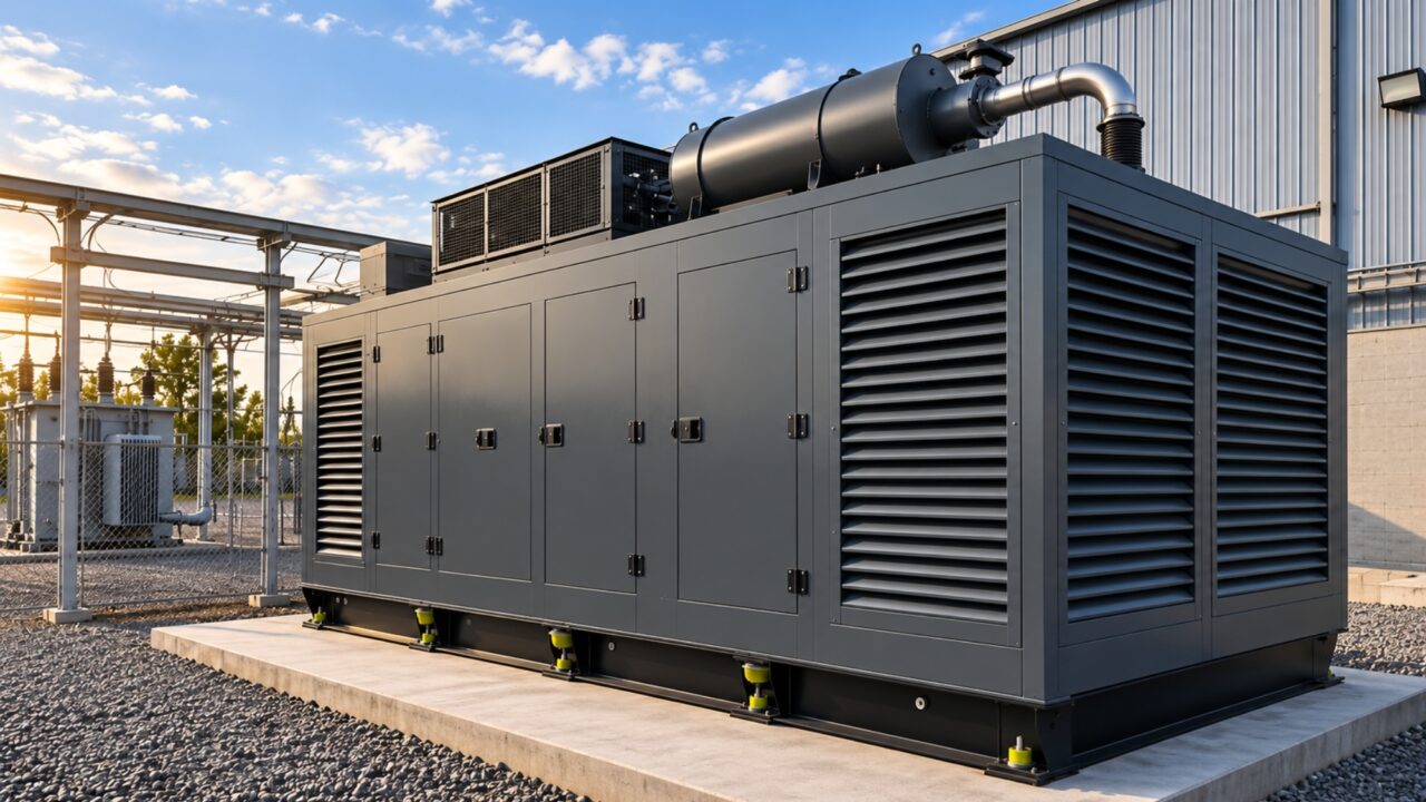
Sound attenuated panels are layered acoustic assemblies engineered to absorb sound, limit sound transmission, or both. In power generation, acoustic treatment must reduce noise without compromising cooling airflow, exhaust routing, service access, or equipment operation. Those conditions should define the acoustic architecture before the project team selects a complete enclosure, modular panel system, or combination of treatments.
Generator Noise Is a System of Sources and Paths
Generator noise rarely behaves like a single source that can be solved by surrounding the machine with one layer of material. Engine surfaces, cooling fans, radiator openings, exhaust systems, ventilation paths, and structural connections can each contribute to what reaches workers, adjacent rooms, or nearby properties. Effective attenuation starts by identifying which sources dominate and how their energy travels beyond the equipment.
Engine and Block Noise Radiate Through the Acoustic Boundary
Engine and generator surfaces radiate airborne mechanical noise that must be controlled through the acoustic boundary. Depending on the application, the boundary may need sufficient transmission loss to limit sound passing through the assembly and source-side absorption to reduce reflected sound within the treated space. Structure-borne vibration can bypass an airborne acoustic boundary through foundations, piping, ductwork, or other rigid connections, so those paths require separate evaluation.
Radiator and Fan Noise Follow the Cooling-Air Path
Radiator and fan noise presents a different challenge because the same opening that moves cooling air can also become a major acoustic path. The system cannot simply close that opening to gain attenuation, because the generator still has to reject heat at the airflow required by the equipment. Intake and discharge design therefore becomes an acoustic and mechanical problem at the same time.
Louvers, attenuators, duct geometry, and discharge configuration can materially affect the acoustic and airflow performance of the assembled system. A wall may provide strong transmission loss, yet an untreated air opening can remain a dominant path. The design has to account for the acoustic performance of the opening and the resistance it adds to the cooling-air system.
Exhaust and Airflow Noise Require Their Own Treatments
Exhaust noise follows its own path and generally requires treatment on the exhaust side of the system. Mufflers, silencers, and related components address that source in a way wall panels cannot. Wall panels can control sound through the acoustic boundary, but exhaust and ventilation paths require treatments designed for those openings and flow paths.
Turbulent airflow through fittings and sound-attenuating elements can generate aerodynamic noise, especially as velocity and turbulence increase. The design goal is to reduce transmitted sound without creating excessive restriction or unnecessary regenerated noise.
The Acoustic Boundary Should Follow the Application
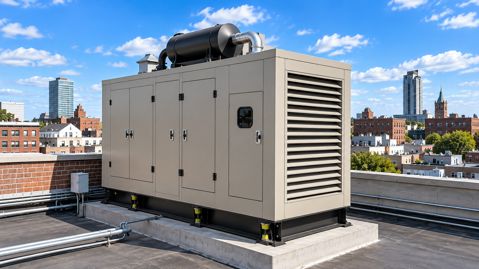
The physical form of a noise-control system should be selected after the important sound paths and operating constraints are understood. A complete enclosure can be the right architecture for a packaged genset with known clearances, ventilation, exhaust routing, and service access. Other installations need the acoustic boundary to adapt to conditions that already exist.
Complete Enclosures Still Fit the Right Applications
Drop-over, skid-mounted, and field-erected generator enclosures can provide a defined acoustic boundary around a generator package. They make sense when equipment layout, available space, ventilation, access requirements, and project conditions support that configuration. They can also integrate acoustic louvers, attenuators, exhaust treatments, doors, and removable sections as part of a coordinated system.
Starting with a fixed enclosure concept before the dominant sound paths, cooling-air requirements, and site geometry are known can force the rest of the design to accommodate that product form.
Modular Panels Expand the Available Geometry
Modular panels allow engineers to define the acoustic boundary around the installation itself. They can form partial enclosures, standalone walls, barriers, plenums, partitions, or complete field-assembled structures around gensets, engine rooms, and equipment areas within larger power plants. For retrofits, tight equipment rooms, and custom enclosure build-outs, field-assembled panel systems can provide added layout flexibility when a preconfigured drop-over or skid package cannot accommodate existing site conditions.
Panel Performance and Installed Performance Are Different Questions
Laboratory panel performance is an important design input, but it is not a prediction of the final sound level around an operating generator. The assembled system includes walls, joints, doors, ventilation openings, exhaust penetrations, access points, and other paths that can influence the installed result. Engineers therefore need to distinguish component ratings from whole-system performance.
Layered Construction Controls Absorption and Transmission
Dynasonics' standard acoustical panel construction combines a solid galvanized-steel outer skin, internal acoustic fill, structural framing, and a perforated inner surface. The solid face helps resist sound transmission, and the absorptive core helps control acoustic energy on the source side. Dynasonics' standard panels use rugged galvanized-steel construction, with acoustic fill mechanically retained for severe vibration conditions encountered during operation.
Openings and Leakage Can Control the Final Result
The performance of an acoustic boundary can be limited by an untreated path that bypasses the panel assembly. A panel wall can have strong laboratory transmission-loss data, yet sound may still escape through ventilation openings, door gaps, penetrations, exhaust routes, or poorly sealed joints. Increasing the wall rating alone will not solve a path that bypasses the wall.
Airflow and Pressure Drop Belong in the Acoustic Design
Generator cooling places practical limits on the resistance that can be added to intake and discharge paths. Acoustic components in those paths have to be selected within the airflow capability of the cooling system.
Every Ventilation Opening Creates an Acoustic Path
An intake or discharge opening is necessary mechanically, but acoustically it is also a break in the enclosure boundary. The engineer needs enough free area and acceptable resistance for airflow, along with enough acoustic attenuation to keep the opening from dominating the overall noise condition. Radiator discharge deserves particular attention because it can combine high airflow with significant fan and engine noise.
Restriction Must Stay Within the Cooling System's Capability
Pressure drop should be evaluated as part of the ventilation system, not as an afterthought during acoustic detailing. Each airflow-path component contributes to total resistance, and excessive combined restriction can reduce cooling airflow below the equipment requirement. The target is to meet the noise requirement without exceeding the pressure drop the cooling system can tolerate.
A quiet enclosure that overheats the generator is not a successful acoustic design.
Retrofit Conditions Reveal the Value of Configurability
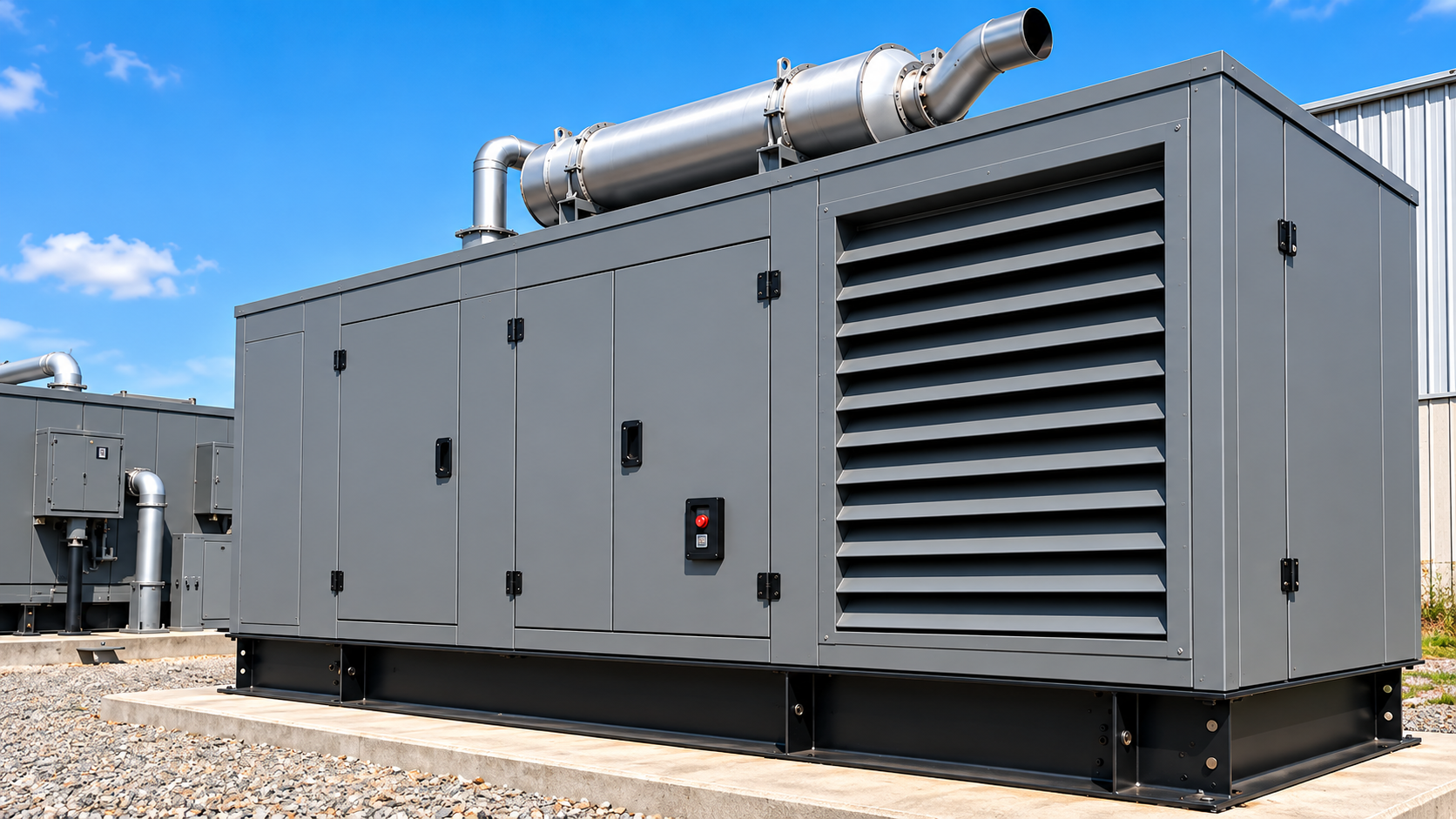
Retrofit projects often require the acoustic boundary to fit conditions that cannot be moved or redesigned.
Existing Rooms Rarely Behave Like Blank-Sheet Enclosure Projects
Consider a generator already operating in a tight mechanical room. The team may need to reduce sound leaving one side of the room, control a radiator discharge path, preserve access to service points, and work around utilities that cannot be relocated. A full drop-over enclosure may still be possible, but it is no longer the only useful design model.
The better question is where an effective acoustic boundary can be built without interfering with operation. In some cases, the existing room can become part of that boundary. In others, panels, access sections, ventilation attenuation, and localized treatment can be combined around the site.
Field-Assembled Systems Can Work Around Existing Constraints
Field-assembled equipment enclosures allow the acoustic structure to be developed around existing equipment and facility conditions. Panels can be arranged around access requirements, structural elements, ventilation paths, and irregular footprints, with doors, louvers, attenuators, or removable sections integrated where required. In a retrofit, the room itself becomes part of the acoustic design.
That changes the role of the panel from an enclosure component to a building block of the acoustic boundary.
Start With Four Questions Before Selecting the Acoustic Architecture
Before selecting a complete enclosure, modular panel system, or combined treatment, engineers should answer four questions about the installation:
- Which Noise Sources and Transmission Paths Dominate? Identify the engine, radiator/fan, exhaust, ventilation, and structural paths driving the noise condition.
- What Airflow and Pressure-Drop Requirements Must Be Preserved? Establish required cooling airflow and allowable system restriction before selecting intake or discharge attenuation.
- What Geometry, Access, and Existing Infrastructure Constrain the Acoustic Boundary? Map equipment, utilities, penetrations, service areas, and structural conditions that affect the available configuration.
- Which Acoustic Architecture Fits Those Conditions? Select a complete enclosure, modular panel system, partial treatment, or integrated combination based on the preceding requirements.
This sequence gives engineers a practical basis for comparing configurations before committing to an enclosure form.
Better Noise Control Starts With the Right Acoustic Architecture
Power-generation noise control should begin with the installation conditions that define the acoustic boundary. Dynasonics' acoustical panel assemblies are supported by independently tested transmission-loss and absorption data, and its equipment and generator enclosures are engineered around the acoustic, airflow, access, and site requirements of power-generation environments.
Frequently Asked Questions About Sound Attenuated Panels in Power Generation
The answers below address where panels fit, what their test data can tell engineers about noise reduction, and when modular construction suits the installation.
What Are Sound Attenuated Panels Used for in Power Generation?
Sound attenuated panels are used to absorb and block radiated equipment noise and to create acoustic boundaries around generators, engines, and associated mechanical equipment. Depending on the application, they can form full enclosures, partial enclosures, barriers, plenums, partitions, or wall systems. Their modular construction is particularly useful where the boundary has to fit existing equipment or room geometry.
How Much Noise Reduction Do Acoustic Panels Provide on a Generator?
There is no universal dB reduction that applies to every generator installation. Laboratory transmission-loss and absorption data describe the performance of the panel assembly, but installed attenuation also depends on the generator's noise spectrum, enclosure geometry, joints, doors, penetrations, ventilation paths, exhaust treatment, vibration paths, leakage, and site conditions. Project-level noise targets therefore need to be evaluated at the system level rather than inferred from one panel rating.
When Should Engineers Consider Panels Instead of a Complete Generator Enclosure?
Modular panels deserve consideration when the acoustic boundary needs to adapt to an existing installation, constrained mechanical room, irregular footprint, partial treatment area, or custom ventilation and access arrangement. A complete enclosure may remain the better fit for a packaged installation with compatible space and operating conditions. The choice should follow the noise paths, airflow requirements, geometry, and service needs of the project.